English
 Español

Need Help Now? Call Us!
+86-573-8553-5198
Need Help Now? Call Us!
+86-573-8553-5198
Our team proudly offers an on-time guarantee and a 100% customer satisfaction guarantee.
Contact Online


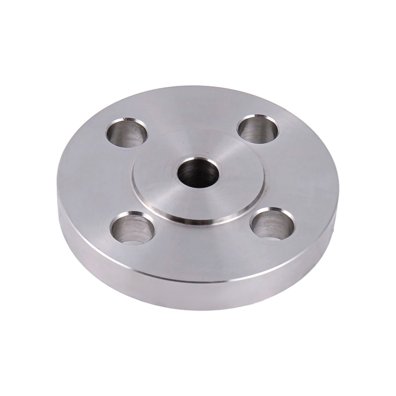
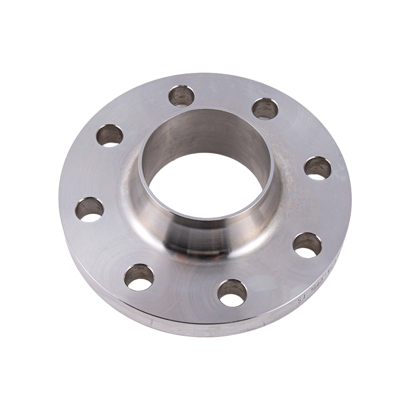
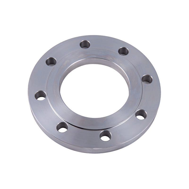
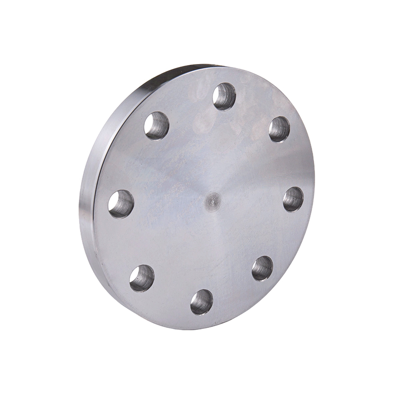
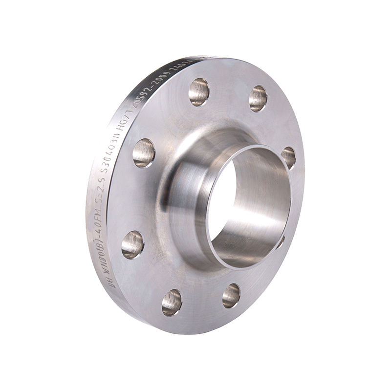
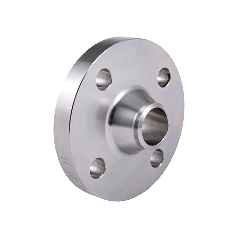
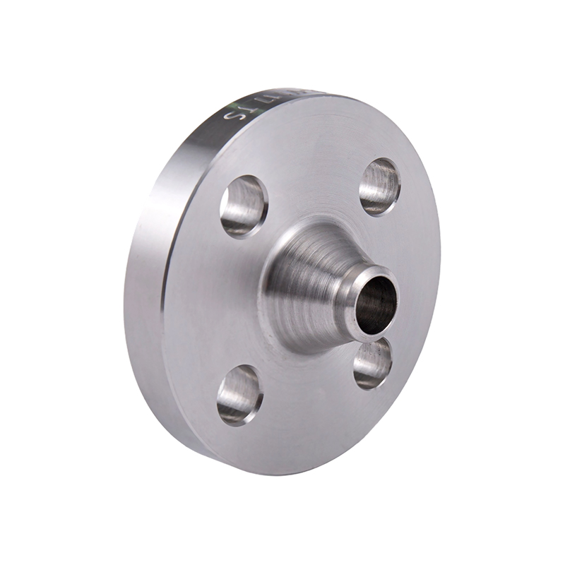
An ANSI standard weld neck forged flange is the preferred choice for demanding piping applications because its tapered hub provides a smooth stress transition from the flange face to the pipe wall, eliminating the abrupt discontinuity that causes turbulence and fatigue failure in other flange types. The flange is attached to the pipe by a full-penetration butt weld at the hub end, creating a joint that is as strong as the pipe itself and can be radiographically inspected to verify weld integrity. This design feature, combined with the grain flow orientation achieved through the forging process, makes the weld neck flange the only flange type universally accepted for critical high-pressure, high-temperature, and cyclic-loading services in the petroleum, petrochemical, and power generation industries. When specified to an ANSI standard—most commonly ASME B16.5 for pipe sizes up to 24 inches and ASME B16.47 for larger diameters—the flange dimensions, pressure-temperature ratings, and material requirements are fully standardized, ensuring interchangeability with valves, fittings, and equipment from any manufacturer worldwide.
Content
The forging process fundamentally alters the internal structure of the steel in ways that casting or machining from plate cannot replicate. A forged flange begins as a billet of steel—a cast ingot or a continuously cast bloom that has been hot-worked to close internal porosity—and is shaped under immense compressive force between forging dies. This deformation elongates the non-metallic inclusions and the grain boundaries in the direction of metal flow, creating a continuous grain flow pattern that follows the contour of the flange. The aligned grain structure resists crack propagation perpendicular to the applied stress, giving the forged flange superior fatigue resistance and impact toughness compared to a cast or plate-cut flange where the grain orientation is random or perpendicular to the primary stress direction.
For a weld neck flange specifically, the forging process is designed so that the grain flow lines run continuously from the flange face up through the tapered hub and into the weld bevel. This means that when the flange is butt-welded to a pipe, the grain flow in the flange and in the pipe are aligned, creating a metallurgically homogenous joint. The absence of a weak boundary layer—a characteristic of cast structures where the surface chill zone meets the columnar grain zone—means there is no preferential failure path. For critical services such as hydrogen service, sour gas processing, or high-temperature steam, this continuous grain structure is essential to prevent the embrittlement and cracking that can initiate at microstructural discontinuities.
The ANSI standard that governs weld neck flanges—now published by ASME as ASME B16.5—organizes flanges into pressure classes that define the maximum allowable working pressure at a given temperature for a given material. The standard pressure classes for weld neck flanges are 150, 300, 400, 600, 900, 1500, and 2500. The class number is not the working pressure in psi; it is a designation that correlates to a pressure-temperature rating table. A Class 300 flange in carbon steel (ASTM A105) at ambient temperature has a working pressure limit of approximately 740 psi (51 bar), while the same flange at 400°C (750°F) is derated to approximately 635 psi (44 bar). At the extreme end, a Class 2500 flange in alloy steel can withstand pressures exceeding 6,000 psi at ambient temperature.
The dimensional characteristics that distinguish each pressure class are the flange thickness, the hub diameter at the base, the bolt circle diameter, and the number and size of the bolt holes. As the pressure class increases, these dimensions increase to handle the greater mechanical loads, even though the nominal pipe size remains the same. The table below illustrates how the key dimensions scale with pressure class for a common 4-inch (DN 100) weld neck flange.
| Pressure Class | Flange OD (mm) | Flange Thickness (mm) | Hub Base Diameter (mm) | Number of Bolts | Bolt Diameter (mm) | Approx. Weight (kg, A105) |
|---|---|---|---|---|---|---|
| Class 150 | 228.6 | 23.9 | 117.3 | 8 | 19.1 (3/4") | 7.7 |
| Class 300 | 254.0 | 31.8 | 130.0 | 8 | 22.2 (7/8") | 13.2 |
| Class 600 | 273.1 | 38.1 | 152.4 | 8 | 25.4 (1") | 19.9 |
| Class 900 | 292.1 | 44.5 | 177.8 | 8 | 31.8 (1-1/4") | 28.5 |
| Class 1500 | 311.2 | 54.0 | 203.2 | 8 | 38.1 (1-1/2") | 43.2 |
The bore of a weld neck flange is machined to match the nominal pipe wall thickness of the connecting pipe. This means that for a given nominal pipe size, flanges with different bore diameters are available to match standard, extra-strong (XS), and double extra-strong (XXS) pipe schedules. The bore tolerance is specified in the standard, and the weld bevel at the hub end is machined to a 37.5-degree angle with a root face of approximately 1.6 mm, per ASME B16.25, to create a standard V-groove for the butt weld joint.
The material from which a weld neck flange is forged determines the temperature and pressure limits of the finished component and its resistance to specific corrosion mechanisms. ASME B16.5 references the ASTM material specifications, and the pressure-temperature rating tables are organized by material group. The selection of the material is a decision based on the design temperature, the design pressure, the fluid chemistry, and the potential for environmental cracking mechanisms such as sulfide stress cracking in sour service or chloride stress corrosion cracking in austenitic stainless steels exposed to hot chlorides.
The most commonly specified forging materials for ANSI weld neck flanges and their typical application envelopes are:
The flange facing—the geometry of the sealing surface on the flange face—is selected based on the pressure class, the fluid characteristics, and the gasket type. The ANSI standard defines several facing types, each with a specific application domain. The most common facings on weld neck flanges are:
The standard facing for Class 150 and 300 flanges, consisting of a raised plateau approximately 1.6 mm (1/16 inch) high for Class 150 and 300 and 6.4 mm (1/4 inch) high for Class 400 and above. The raised face concentrates the bolt load onto a smaller gasket area, increasing the contact pressure and improving the seal. The surface finish of the raised face is specified by the standard as a serrated concentric or spiral groove pattern with a surface roughness of 3.2 to 6.3 µm Ra (125 to 250 microinch AA). This serrated finish bites into the soft gasket material and prevents it from being extruded out of the flange joint under pressure.
The standard facing for high-pressure flanges from Class 600 through Class 2500 in critical service. The flange face has a precision-machined groove that accepts a solid metal ring gasket—typically oval or octagonal in cross-section—made from a material that is softer than the flange material. When the bolts are tightened, the ring gasket is plastically deformed into the groove, creating a metal-to-metal seal that is capable of containing pressures exceeding 10,000 psi and temperatures beyond 500°C. The RTJ gasket is the only gasket type accepted for high-pressure steam, boiler feedwater, and hydrocarbon services where a gasket blowout would have catastrophic consequences. The standard ring gasket materials are soft iron (for carbon steel flanges), 304 or 316 stainless steel, and various nickel alloys for corrosive and high-temperature services.
Used primarily for Class 125 cast iron flanges and for connections to flat-faced equipment nozzles where a raised face flange would bend and crack the mating cast iron flange when the bolts are tightened. A full-face gasket, extending to the bolt circle, is used with flat face flanges to distribute the bolt load evenly across the entire face area.
The installation of a weld neck flange onto a pipe requires a full-penetration, single-V groove butt weld that joins the machined bevel at the end of the flange hub to the matching bevel on the pipe end. The weld is typically performed using the gas tungsten arc welding (GTAW) process for the root pass to ensure complete penetration and a clean, oxide-free root surface, followed by shielded metal arc welding (SMAW) or flux-cored arc welding (FCAW) for the fill and cap passes. The welding procedure specification (WPS) must be qualified per ASME Section IX, and the welder must be qualified for the specific material, thickness, and position.
The critical welding consideration for weld neck flanges is the control of the heat-affected zone (HAZ) in the flange hub. The flange hub near the weld is subject to a complex thermal cycle that can alter its microstructure, induce residual stresses, and, for certain alloy steels, create a hard, brittle martensitic zone if the cooling rate is too rapid. For chromium-molybdenum alloy steel flanges (ASTM A182 F11, F22), preheating to 200°C to 300°C (400°F to 575°F) is mandatory before welding to slow the cooling rate and prevent martensite formation, and a post-weld heat treatment (PWHT) at 675°C to 730°C (1250°F to 1350°F) for one hour per 25 mm of weld thickness is required to temper the HAZ, relieve residual stresses, and restore the material's fracture toughness. The PWHT of a welded flange-pipe assembly is performed on the completed weld, and the hardness of the HAZ is verified by portable hardness testing per ASTM E110 to confirm that the hardness is below the specified maximum—typically 225 HBW for P-No. 4 and P-No. 5A alloy steels in refinery service.
A weld neck flange manufactured to an ANSI standard is supplied with a set of mandatory and optional quality documents that verify its compliance with the material and dimensional specifications. The Material Test Report (MTR) or mill certificate is the primary document, certifying the heat number of the forging, its chemical composition, its tensile strength, yield strength, elongation, and reduction of area from a tensile test, and its hardness. For low-temperature carbon steel flanges (A350 LF2), the MTR also includes the Charpy V-notch impact test results at the specified test temperature. For stainless steel flanges, the MTR includes the intergranular corrosion test results when specified. The MTR must be traceable to the flange by the heat number, which is stamped on the periphery of the flange along with the material grade, the pressure class, the nominal pipe size, and the manufacturer's identification mark per the marking requirements of ASME B16.5.
Non-destructive examination of the finished flange includes visual inspection of the machined surfaces, the facing, and the weld bevel for laps, seams, cracks, and other surface discontinuities per MSS SP-55. For critical-service flanges, additional NDE is specified: liquid penetrant examination (PT) or magnetic particle examination (MT) of the flange face, the hub-to-face transition, and the weld bevel per ASME B16.5 paragraph 8.3; and ultrasonic examination (UT) of the entire forging volume per ASTM A388 or the applicable ASTM forging specification to detect internal defects such as inclusions, voids, or laminations. The acceptance criteria for these examinations are defined by the applicable ASTM forging standard and the purchaser's supplementary requirements.
The assembly of an ANSI weld neck flange joint requires controlled bolt tightening to a specified torque or bolt stress to achieve the gasket compression necessary for a leak-free seal without over-stressing the flange, the bolts, or the gasket. The bolts are tightened in a cross-pattern sequence—also called a star pattern—in at least three passes of increasing torque: 30%, 60%, and 100% of the target torque. This progressive tightening ensures that the gasket is compressed uniformly and prevents the flange from cocking, which would create a wedge-shaped gap that the gasket cannot fill.
The target bolt torque is calculated from the gasket seating stress, the gasket contact area, the bolt material yield strength, and the friction coefficient of the bolt threads and the nut bearing surface. The target bolt stress is typically 40% to 70% of the bolt material yield strength for standard gaskets, with the lower end of the range used for soft gaskets like compressed fiber or PTFE and the higher end for metal and spiral-wound gaskets. Lubrication of the bolt threads and the nut bearing surfaces with a high-pressure anti-seize compound is essential to achieve a consistent relationship between torque and bolt tension; unlubricated threads can consume 50% or more of the applied torque in friction, resulting in a bolt preload that is significantly lower than the calculated value. For critical flanged joints in ASME B31.3 process piping, the bolt tightening procedure is a documented part of the quality assurance process, and the bolt torque values are recorded on a flange joint integrity report.
Products
Contact info.
+86-573-8553-5198
+86-136-1655-8299
+86-573-8553 5198
No. 207, Chuangye Road, Zhapu Town, Pinghu City, Zhejiang Province, China
QR Code
 Forged Stainless Steel Flanges Suppliers